

 English
 Español


Industry News
Home / News / Industry News / How to Injection Mold Plastic Parts: The Complete Step-by-Step Guide for Engineers
Content
You are holding the first prototype of your new product. It feels right in your hand, the textured surface matches the design intent, and the functional test passed. Now you need 200,000 of them, at a cost that keeps your margin healthy, delivered on a schedule that does not push back the launch date. This is the moment when the question becomes concrete: how do you injection mold this plastic part, and how do you do it without costly surprises? The answer is not just about buying machine time. It is about the entire chain of decisions that starts with the part drawing and ends with a repeatable production process. This guide walks through that chain in practical terms, written for product engineers, purchasing managers, and business owners who need real answers rather than theory.
Plastic injection molding is the dominant manufacturing process for mass-produced plastic parts because it delivers unmatched repeatability, speed, dimensional consistency, and freedom of form. But the same process that produces flawless medical components by the millions can also produce scrap by the truckload when the fundamentals are ignored. The fundamentals are simple to list but demanding to execute: a part designed for molding, a mold built from the right steel with the right cooling and gating, a material selected for the real service conditions, a machine sized correctly, and a process window that is understood and documented. Whether you plan to operate your own molding line or hand the project to an experienced contract molder, these fundamentals decide your success.
Injection molding is a manufacturing process in which thermoplastic or thermoset polymer pellets are melted, injected under high pressure into a closed metal mold, cooled until solid, and then ejected as a finished or near-finished part. The mold contains the negative shape of the part, and every detail on the part surface—texture, lettering, undercuts, bosses, ribs—must be engineered into that steel cavity before the machine ever runs.
The process earns its position as the default choice for high-volume plastic parts because of a combination that few other processes can match. Cycle times are measured in seconds or tens of seconds, not minutes. Dimensional repeatability is excellent: a well-designed mold can hold tolerances of a few hundredths of a millimeter across millions of shots. Surface finish can be polished to a mirror gloss or textured to match a customer's specified grain. Automation around the machine, including robotic part removal and conveyor-based inspection, turns the process into a low-labor operation. The per-part cost continues to fall as volume rises, which is the exact opposite of machining or 3D printing.
The practical consequence is a clear volume threshold. Below a few thousand parts, injection molding is rarely the cheapest option because the mold itself is expensive. Above ten thousand parts, injection molding usually beats every alternative on total cost, and above a hundred thousand parts, there is simply no serious competition. The decision to mold is therefore a decision about volume, quality consistency, and the confidence that the part design is stable enough to justify tooling.
Every injection molded part is produced by the same basic cycle. Understanding the cycle is essential because every defect and every cost problem can be traced back to one of these stages. The cycle repeats continuously, and the time it takes to complete one cycle is called the cycle time. Cycle time directly determines how many parts come out of the machine per hour, which is the biggest factor in unit cost.
| Stage | What Happens | Typical Share of Cycle Time |
|---|---|---|
| Clamping | The mold closes and the machine builds up clamping force to hold the two halves shut against internal injection pressure. | 5 to 10 percent |
| Injection | The screw moves forward like a plunger, pushing molten polymer through the nozzle and into the cavity. | 5 to 15 percent |
| Packing and holding | Pressure is maintained to push extra material into the cavity and compensate for shrinkage as the polymer cools. | 5 to 20 percent |
| Cooling | The part solidifies inside the mold while heat is removed by cooling channels in the steel. | 50 to 70 percent |
| Ejection | The mold opens and ejector pins push the solidified part out of the cavity. | 5 to 10 percent |
Most engineers new to molding focus on the injection stage, but the cooling stage is where the economics are decided. Because cooling takes up the largest share of the cycle, mold designers spend enormous effort on cooling channel layout. A mold with poorly placed cooling lines will produce parts unevenly, with warpage and long cycle times. A mold with well-designed cooling can cut cycle time by 20 to 40 percent compared to an average layout, which multiplies directly into cost savings over the life of the tool.
Packing pressure deserves equal attention. When the cavity is filled, the polymer begins to shrink as it cools. If no additional material is pushed in, the part will develop sink marks on thick sections and internal voids. Holding pressure pushes more melt into the cavity to compensate. The tricky part is that too little holding pressure causes sinks, and too much causes flash—thin fins of plastic that squeeze out at the parting line. Finding the balance is the core skill of a molding technician.
If you are setting up an injection molding process from scratch, the workflow follows a logical sequence. Each step has its own pitfalls, and skipping any of them guarantees problems later.
Molding problems usually start on the drawing board. Wall thickness should be kept uniform wherever possible, typically between 1.5 mm and 4 mm, because thick sections cool slowly, sink, and void, while thin sections resist flow and may not fill. Every vertical surface needs draft, usually 0.5 to 2 degrees per side, so the part can be released from the mold without being scratched or stuck. Sharp inside corners concentrate stress and cause cracking; a radius of at least 0.5 mm should be added. Ribs used for stiffness should be thinner than the wall they attach to, typically 50 to 70 percent of the nominal wall thickness. Bosses for screws need generous fillets at the base. These design rules cost nothing on paper but eliminate most of the quality problems that appear later.
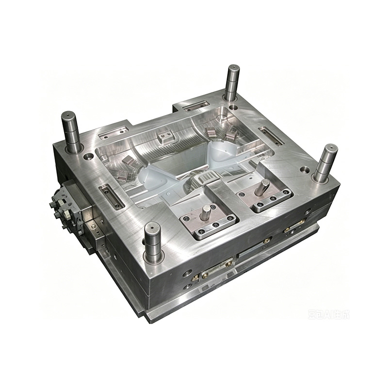
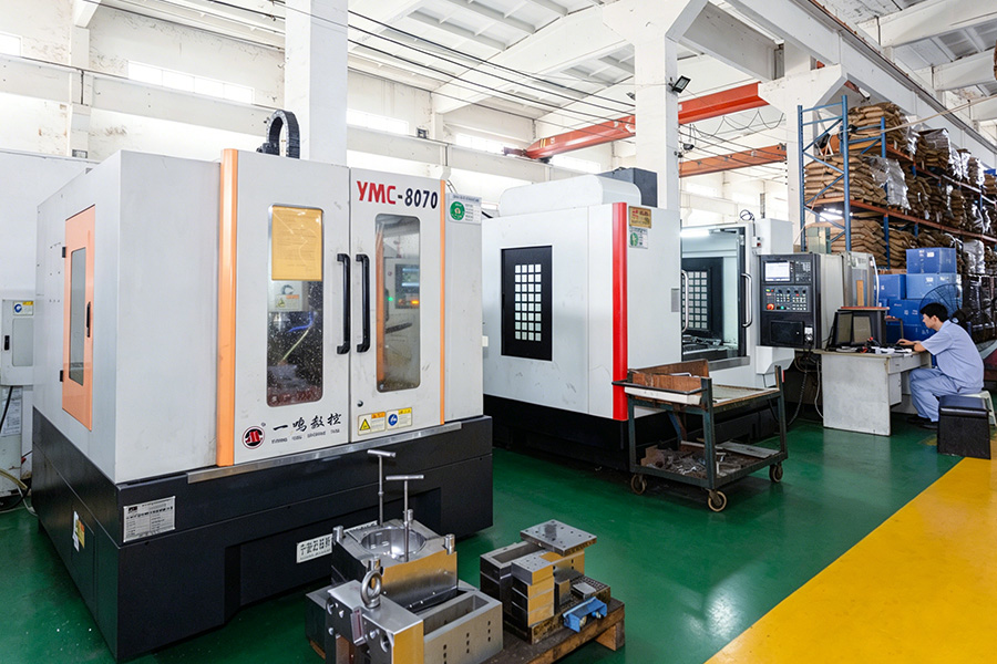
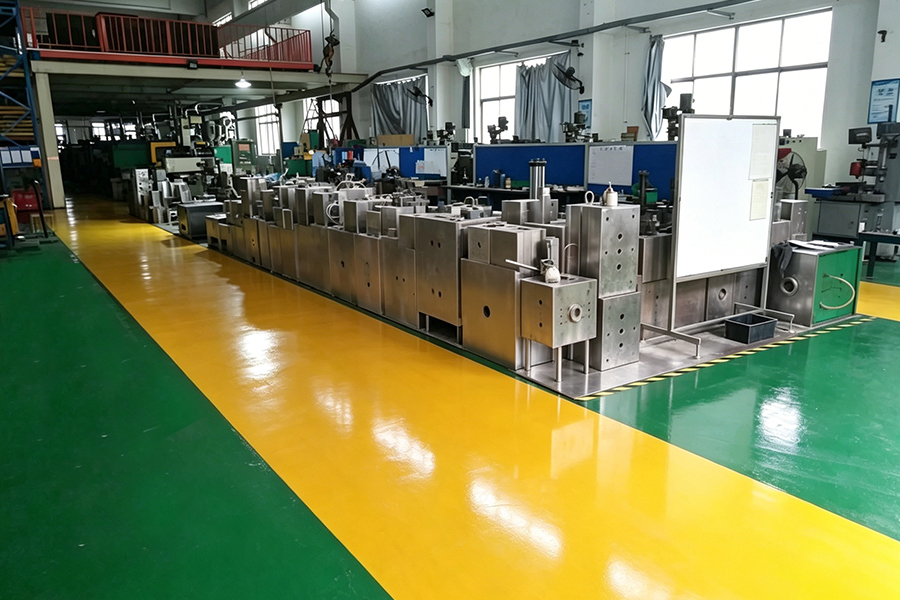
The mold is the heart of the entire operation. A typical production mold has a steel frame, a cavity side and core side that form the part shape, cooling channels, runners and gates to deliver melt, and an ejector system to push the part out. The number of cavities determines how many parts are made per cycle: a one-cavity mold for a pilot run, a four-cavity or eight-cavity mold for production, and up to dozens of cavities for tiny parts like electronics connectors. Tool steel selection matters. P20 is a common pre-hardened steel for general-purpose molds. H13 is used when the mold must survive abrasive glass-filled materials or high molding temperatures. S136 stainless steel is chosen for medical and optical applications where corrosion resistance and a polished surface are required. The mold maker's job includes cutting the cavity by CNC machining or electrical discharge machining, polishing the surface, installing inserts and slides for undercuts, and tuning the ejection system. A mold built poorly will never produce a good part, no matter how capable the machine or operator.
Plastic material selection is a constraint-matching exercise. The resin must survive the operating temperature of the part, resist the chemicals it will contact, have the required mechanical strength and impact toughness, meet flammability or food-contact regulations, and flow well enough to fill the mold. For a production mold, one additional factor dominates: shrinkage. Every polymer shrinks as it cools from melt temperature to room temperature, and the mold cavity must be made larger than the final part dimension by exactly the shrinkage amount. Polypropylene shrinks roughly 1.5 to 2.5 percent, while amorphous materials like polycarbonate shrink only about 0.5 to 0.7 percent. Glass-filled grades shrink less and more predictably in the flow direction. The molder needs the precise shrinkage data for the specific grade, because a mismatch between assumed shrinkage and the chosen material is one of the most common causes of out-of-tolerance parts.
The process window is the combination of machine parameters that produces acceptable parts: melt temperature, mold temperature, injection pressure, injection speed, holding pressure, holding time, cooling time, back pressure, and screw rotation speed. Melt temperature must be high enough that the resin flows without degrading; running the barrel too hot burns the polymer and produces brown streaks or brittle parts. Mold temperature controls the cooling rate and the surface finish; a hot mold gives a better cosmetic appearance and lower molded-in stress, but a longer cycle. Injection speed must be matched to the geometry: thin walls need fast injection, but extremely fast injection through a restrictive gate can cause burn marks. Every parameter interacts with every other, so the best practice is to run a design of experiments, or at least a systematic series of trial shots, to establish a process window that is robust to normal variation in resin batch and ambient conditions.
Once the process window is established, the first shots are inspected carefully. Dimensional measurements are taken with CMM or hand tools, surface finish is compared to the approved standard, and functional samples are tested. Trial stages follow an industry convention: T0 is the first sampling from a new mold, often revealing flash, short shots, or ejection problems; T1 is the mold review after modifications; T2 is the corrected trial that should produce parts meeting the agreed specifications. Only after customer approval of samples should mass production begin. Even in mass production, the process is monitored with a process log, and parts are checked at defined intervals. The discipline of documenting every parameter and every inspection result is what separates a controlled process from trial and error.
Many buyers treat the mold as a commodity, yet the mold is where nearly all part quality is determined. Every hidden decision in the mold design office will show up in the parts, in the cycle time, and in the maintenance bill over the mold's lifetime.
Steel selection is the first trade-off. Pre-hardened steels around 28 to 36 HRC are easy to machine and adequate for standard thermoplastics like ABS, PP, and PS. Engineering plastics with abrasive fillers, such as 30 percent glass-filled nylon, wear a soft cavity like sandpaper, so the tool should be made in H13 or hardened tool steel, or at least fitted with wear-resistant inserts in high-abrasion zones. For cosmetic parts molded in transparent resins, the cavity surface must be polished to a high gloss; a stainless steel or a steel that will accept fine polishing is required. Selecting the wrong steel to save money on tooling is a classic false economy because the mold wears out, corrodes, or fails to match the product's appearance standard long before the production run ends.
The gate is the entry point where molten plastic passes from the runner into the cavity. Its size, shape, and location control how the material flows, and therefore the appearance of the finished part. An edge gate, the most common type, is cut into the parting line and leaves a small mark that must be trimmed. A tunnel or sub-gate is located below the parting line and is sheared off automatically during ejection, reducing secondary labor. A pin gate is a small orifice that breaks cleanly for aesthetic parts. A fan gate spreads the flow for wide, flat parts. The gate location determines where weld lines appear: wherever two flow fronts meet, a knit line forms that is weaker and visually visible. The designer must place the gate so that weld lines land in low-stress, low-visibility areas. A center gate on a round part gives balanced radial flow, while an off-center gate on an asymmetric part will cause overpacking on one side and sink marks on the other.
The runner is the channel that carries melt from the machine nozzle to the gates. In a cold runner system, the runner solidifies with the part and is reground as scrap, which slightly degrades the material and adds labor. In a hot runner system, the manifold inside the mold is heated and the runner stays molten between cycles, eliminating runner scrap and reducing cycle time. Hot runners pay for themselves on large production runs, especially with expensive resins, but they add significant mold cost and require more skill to maintain. For a new project, the molder should model the cost carefully: hot runner tooling may add tens of thousands of dollars to the mold budget, but if the part is a commodity resin with only a few thousand shots per year, a cold runner and a regrind strategy is the pragmatic choice.
Cooling is the first place to look if a mold runs a slow cycle. Cooling channels should follow the contour of the part as closely as possible, which is why modern mold shops often use conformal cooling with 3D-printed inserts. Traditional straight-drilled channels are cheaper but may leave hot spots behind thick sections. Because heat extraction is two-sided, both the cavity and the core need cooling, and the core side of a cup-shaped part is the side where heat collects most easily. Venting also demands respect. When the melt enters the cavity, trapped air has nowhere to escape if venting is insufficient; the compressed air heats up and burns the plastic, causing charred streaks at the end of fill. Vents are shallow channels at the parting line, no more than 0.03 mm deep for unfilled materials, just enough to let air out but not plastic in.
Many products today demand two colors or two materials in a single part. A soft-touch handle, a colored button with a rubber seal, or a cup with a contrasting gripping band cannot be made in one conventional injection unit. Two-shot molding uses a special machine with two injection units and a rotating platen. The first material is molded, then the mold rotates and the second material is injected around or over the first. The result is a permanent molecular bond between the two materials, eliminating the need for assembly and adhesive. For everyday products like a two-color cup, the process creates a clean line between colors that is impossible to achieve by printing or pad printing. Molds for two-shot work must be engineered more carefully, because both the first and second cavities must index accurately, and the shrinkage of both materials must be compatible enough to avoid stress at the interface.
 Two-Color Injection Molds for Cups with Soft-Touch LayersThese molds produce cups by integrating food-grade PP or PC with soft TPE or silicone, creating a permanent bond and eliminating secondary assembly. They support custom non-slip textures and logos, making them ideal for thermal flasks, sports bottles, and premium gift cups.View Product →
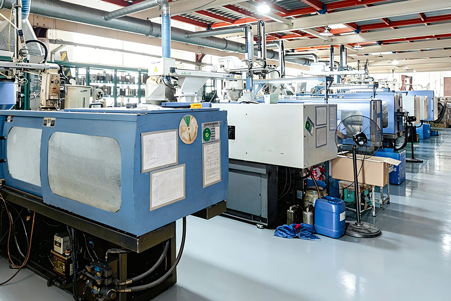
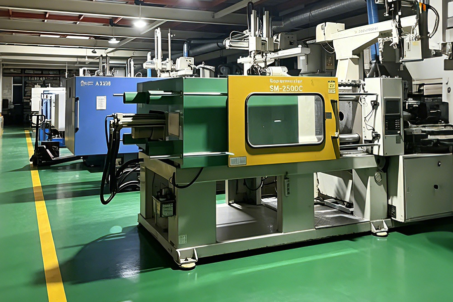
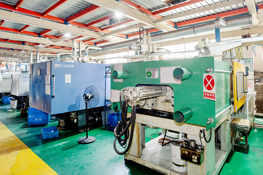
Once the mold is designed, the machine must be matched to it. Three machine specifications matter most: clamping force, shot capacity, and platen size.
Clamping force holds the mold shut against the pressure of the injected plastic. If the machine cannot generate enough tonnage, the mold will open slightly during injection and the part will come out with flash. The required clamping force is approximated by multiplying the projected area of the part plus runner by a cavity pressure factor that depends on the material. Commodity resins like polypropylene need about 3 to 5 tons of clamp per square inch of projected area; engineering resins like nylon and polycarbonate may need 5 to 8 tons. A part with a projected area of 50 square inches in ABS, for example, would need somewhere around 200 to 250 tons of clamping force. The calculation is a rough guide, and the experienced molder adds safety margin for unforeseen packing pressure, but it sharply reduces the risk of being caught with a short clamp.
| Material Family | Typical Cavity Pressure | Clamping Force per Square Inch of Projected Area |
|---|---|---|
| Polypropylene, polyethylene, polystyrene | 400 to 700 bar | 3 to 5 tons/in² |
| ABS, acrylic, SAN | 500 to 750 bar | 4 to 6 tons/in² |
| Nylon, polycarbonate, POM | 600 to 850 bar | 5 to 7 tons/in² |
| Glass-filled engineering resins | 700 to 1000 bar | 6 to 8 tons/in² |
Shot capacity is the next check. The combined volume of all cavities plus the runner system must be no more than about 70 to 80 percent of the machine's maximum shot volume. Running the machine at the edge of its shot capacity risks incomplete filling because the plasticizing unit cannot melt enough material fast enough. Conversely, a machine with a very large barrel running a tiny part will have a problem that is equally bad: the material remains heated so long that it thermally degrades. Platen size and the location of tie bars determine whether the mold physically fits, and the mold height and daylight must match the machine's stroke range. A good molder treats machine selection as a compatibility exercise, not a matter of grabbing whatever press is free.
Most design engineers know the handful of commodity resins and a few engineering grades, but production reality is more demanding. The material specified on the drawing must be available as a commercial grade, must flow well enough for the part geometry, and must shrink within limits that the mold can be built to match.
The first division is between amorphous and semi-crystalline polymers. Amorphous materials like ABS, polycarbonate, and PMMA have randomly arranged molecular chains; they soften gradually, shrink relatively little, and are easier to keep dimensionally stable. Semi-crystalline materials like polypropylene, nylon, and POM have ordered crystalline regions; they shrink more, their shrinkage is anisotropic, and they require more attention to holding pressure and cooling, but they offer better chemical resistance, fatigue life, and bearing properties. The choice between the two families affects not just part performance but every downstream decision about gate sizing, cooling, and tolerance.
| Resin | Typical Mold Shrinkage | Key Characteristics | Representative Parts |
|---|---|---|---|
| Polypropylene (PP) | 1.5% to 2.5% | Low cost, chemical resistance, flexible, fatigue-resistant | Containers, caps, automotive interior trim, household items |
| ABS | 0.4% to 0.7% | Stiff, tough, excellent surface finish, low cost | Appliance housings, consumer electronics, automotive grilles |
| Polycarbonate (PC) | 0.5% to 0.7% | Transparent, impact-resistant, heat-resistant | Lens housings, safety equipment, electrical enclosures |
| Nylon 6/66 (PA6/PA66) | 1.0% to 1.8% | Strong, wear-resistant, low friction | Gears, bearings, under-hood automotive parts |
| POM (Acetal) | 1.5% to 2.5% | High stiffness, excellent dimensional stability, low friction | Precision gears, micro gears, sliding mechanisms |
| PMMA (Acrylic) | 0.3% to 0.6% | Transparent, UV-resistant, scratch-sensitive | Lenses, display windows, lighting covers |
| PC/ABS blend | 0.5% to 0.7% | Balanced impact strength, heat resistance, processability | Automotive interiors, electronic device frames |
Additives broaden the selection further. Glass fibers increase stiffness and reduce shrinkage but wear the mold and cause welded lines to be weaker. Talc fillers reduce cost and warpage. Flame retardants, UV stabilizers, lubricants, and color masterbatch all modify both the part properties and the molding behavior. One common mistake is specifying a filled grade for a cosmetic part without confirming that the surface appearance is acceptable. Another is selecting a material based only on its datasheet without verifying that it meets the required regulatory standard, such as UL94 flammability, FDA food contact, or ISO 10993 biocompatibility for medical devices. Because material changes late in a project can force a re-engineering of the mold, the material specification should be frozen before tooling starts.
Every molding engineer recognizes the standard gallery of defects. They are not random failures; each one has a root cause, usually in the mold design, the material, or the process parameters. A defect that appears in production is a clue, not a mystery, and the corrective action proceeds from diagnosis to change to verification.
| Defect | Symptom | Most Common Causes | Practical Fix |
|---|---|---|---|
| Short shot | Part is incomplete, with missing end-of-fill sections | Insufficient material volume, low injection pressure, restricted gates, premature freezing | Increase injection pressure and shot size; raise mold temperature; enlarge gates; check barrel capacity |
| Flash | Thin fin of plastic protruding along the parting line | Clamping force too low, mold not fully closing, overpacking, worn parting line | Raise clamping tonnage; repair mold surfaces; reduce injection and holding pressure |
| Sink marks | Local depressions on the surface above thick sections | Thick wall sections cooling slower, insufficient holding pressure or time | Redesign ribs and bosses; increase packing; reduce wall thickness; move ribs to hidden side |
| Weld line | Visible line or weak point where two flow fronts meet | Melt meeting around a core or insert, low melt temperature, poor venting | Relocate gate; raise melt and mold temperature; add venting; use higher injection speed |
| Warpage | Part is twisted or bowed after ejection | Uneven cooling, non-uniform shrinkage, excessive molded-in stress | Balance cooling channels; lower mold temperature difference; add holding time; redesign wall thickness |
| Burn marks | Black or brown streaks near the end of fill | Trapped air compressed and overheated, melt temperature too high, residence time excessive | Add vents; reduce injection speed; lower melt temperature; reduce barrel residence time |
| Jetting | Snake-like streaks on the part surface | Melt entering a large cavity through a small gate and not wetting the wall | Enlarge gate; slow first-stage injection speed; change gate location |
| Ejector pin marks | White or raised spots at ejector locations | Part sticks in cavity, too little draft, ejection too early, pin surface too small | Add dwell time; increase cooling; enlarge draft; enlarge pin diameter or add more pins |
Preventing defects begins before the mold is cut. A design-for-manufacturing review can flag thick sections, poor gate placement, and insufficient draft months before production. Once the mold exists, the molder's job is to find the process window that clears the defect and then control that window against every variable: resin lot, humidity, ambient temperature, and machine performance. Detailed and accessible guidance on identifying the common defects of mold molding and how to fix them helps both engineers and technicians build a shared vocabulary for solving these issues quickly.
Injection molding is precise, but it is not infinitely precise. Every thermoplastic has natural shrinkage variation, and the mold itself flexes under pressure. Tolerance classes help the project team align on what is achievable and what is worth paying for. A commercial tolerance of roughly plus or minus 0.1 mm on small dimensions is achievable with ordinary materials and well-built molds. A fine tolerance of plus or minus 0.05 mm requires tighter control of molding parameters and often higher-cost tooling. Precision tolerances in the range of plus or minus 0.02 mm or better are feasible only for highly stable materials, carefully designed molds, and closely monitored processes, which is why high-tolerance parts carry a cost premium.
Material choice dominates achievable tolerance. Polypropylene, with its high shrinkage and post-mold shrinkage, is difficult to hold to tight dimensions. POM and nylon with fillers shrink more predictably. Amorphous resins like polycarbonate and ABS shrink less and are far easier to control. In every case, the mold cavity must be cut to the compensated dimension, and the compensation factor is validated during the trial runs. If the first article is out of tolerance, the mold is not necessarily wrong; the process parameters may simply be shifting the expansion point. A common correction is adjusting holding pressure to change the amount of material packed into the cavity, which shifts the final dimension over a usable range.
Surface finish is specified using the SPI (Society of the Plastics Industry) scale, from A-1 mirror polish through B-grade fine grit, C-grade medium grit, and D-grade rough textures. For many consumer products, a decorative texture is applied by texturing the mold cavity with chemically etched patterns according to the customer's standard. The surface finish is locked in the mold: once the steel is polished or etched, changing the finish late in the project costs real money and downtime.
Quality control in production molding is not limited to measuring the first article. Good practice includes periodic dimensional sampling, visual inspection for surface defects, and monitoring of key process data such as melt temperature, injection pressure profile, and cycle time. In regulated industries such as medical devices, processes are formally validated with IQ, OQ, and PQ protocols, and every lot is traced from resin batch to finished part. For electrically and mechanically demanding parts like connectors, the dimensional precision of the mold steel is critical because tolerances on pitch and profile are often a fraction of a millimeter, and the mold is built with the same level of care as the parts it will produce day after day.
 High-Temperature Electronic Connector Injection MoldsThese molds use LCP and PA9T materials to achieve thin-wall, high-density connector components with V-0 flame retardancy and dimensional stability. They withstand 260°C reflow soldering and are essential for reliable signal transmission in 5G, automotive, and medical electronics.View Product →
The economics of injection molding separate into two blocks: the mold, which is a capital cost paid once, and the piece price, which is paid over every part. Understanding what drives each block allows you to make trade-offs with your eyes open.
Mold cost is driven primarily by cavity count, complexity, steel grade, and the precision of the tooling. A simple one-cavity mold for a small part in P20 steel may cost in the low thousands of dollars. A complex multi-cavity mold for a large automotive panel, with slides, lifters, hot runner, and hardened steel, can cost ten times as much or more. The experience and hourly rate of the toolmaker are also a factor. The buyer's temptation to choose the cheapest tooling quotation can be expensive if it results in a mold that produces parts with short cavities, unbalanced filling, or frequent maintenance needs.
Piece price includes material, machine time, labor, secondary operations, and overhead. Material cost is roughly the part weight times the resin price, plus runner scrap if a cold runner is used. Machine time is the cycle time multiplied by the hourly rate of the injection machine, which ranges from tens of dollars per hour for small presses to hundreds of dollars for large ones. Labor is minimal in a well-automated line, but secondary operations such as trimming gates, painting, and pad printing can add more cost than the primary molding step. Every extra feature in the part, such as a snap fit that requires careful demolding or an insert that must be loaded manually, adds seconds to the cycle and labor to the process.
| Decision | Effect on Mold Cost | Effect on Piece Price |
|---|---|---|
| Higher cavity count | Increases mold cost significantly | Lowers piece price through higher output per cycle |
| Higher tolerance requirement | Increases machining and inspection cost | May increase scrap and measurement labor |
| Hot runner system | Adds substantial mold cost | Reduces scrap and cycle time, lowering piece price |
| Surface texture requirement | Adds texturing cost and lead time | Usually negligible on piece price |
| Secondary assembly features | Minimal if designed into mold | Eliminates separate assembly labor |
The breakeven calculation is the same every time: divide the mold cost by the savings in per-piece price relative to the alternative process. If the alternative produces a part at a higher cost per unit, the production volume at which the mold pays for itself is the mold cost divided by the per-unit saving. This is the number that justifies the tooling investment, and it should be written into the project plan before the purchase order is issued.
The DIY route to injection molding, using benchtop machines, small hand-operated presses, or 3D-printed molds, has its place. It is a legitimate approach for producing low volumes of parts for prototyping, short pilot runs, field trials, and basic education about the process. A 3D-printed mold can survive a few dozen to a few hundred shots of a low-temperature resin like polypropylene, and the cost of the experiment is low. This is useful when the goal is to validate a design concept or when a startup is trying to conserve cash before committing to a steel tool.
But DIY molding has hard limits. A 3D-printed mold cannot transfer heat well enough to run an efficient cycle, so parts cool slowly and the cycle time is long. The dimensional accuracy of a printed mold is nowhere near that of machined steel, and tolerances beyond a few tenths of a millimeter are not realistic. Material choices are heavily restricted because high-melt-temperature resins destroy a printed tool. Consistency is the biggest risk: a benchtop machine with manual material feeding and hand-operated injection cannot repeat the same cavity pressure and cooling profile shot after shot, so every part is slightly different. For quantities above a few hundred or a few thousand pieces, the per-part time cost and reject rate quickly makes DIY molding uneconomical.
Professional injection molding takes over where the DIY approach stops being practical. A hardened steel production mold runs for hundreds of thousands or millions of shots. Multi-cavity molds produce several parts per cycle. Process monitoring holds melt temperature, pressure, and cooling time within tight bounds. Automated equipment handles part removal and stacking. When the product demands reliability, dimensional consistency, or regulatory validation, these capabilities are not optional. In medical production, for example, a syringe or infusion connector must meet both dimensional and material-safety requirements, and molding under validated conditions with traceability is a requirement of the quality system, not a preference.
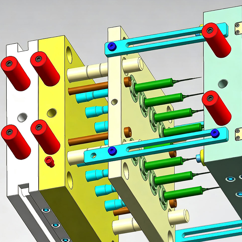 Medical Syringe Injection Molds with Multi-Cavity PrecisionThese molds produce high-transparency syringes from medical-grade PP, PC, or COP, supporting up to 48 cavities for efficient, validated production. They offer biocompatibility, thin-wall uniformity, and sterilization resistance, making them critical for disposable and pre-filled syringe applications.View Product →
The real comparison is therefore not between machinery but between risk and control. Running in-house molding gives a company direct control and avoids the communication gap between molder and product team, but demands capital, floor space, and highly skilled technicians. Working with a professional molder transfers those burdens to a partner whose core competence is the process itself. The buyer should choose a partner that can also design the mold and perform trial runs, because that closes the loop between part design and tooling and reveals manufacturing problems before steel is cut.
When you decide to work with a contract molder, the technical qualification questions matter more than the quoted price. The first question is whether the supplier has an in-house mold shop or outsources tooling. A molder that builds its own molds can react to design changes faster, control tool quality directly, and take responsibility for the interface between mold and machine. A broker who subcontracts the mold to a third party introduces another handoff in the chain and makes accountability ambiguous when something goes wrong.
The second question is equipment range. A serious molder runs presses across a meaningful tonnage spectrum, from small machines for precision components to large presses for panels and structural parts. If the molder only has small presses, your mold must be designed to fit that range, and you will carry unnecessary cost if your part is too large for the biggest available unit. The third question is experience with the relevant material and industry. Medical device manufacturers want a molder that understands clean-room behavior, biocompatibility, and validation protocols, which is why many partner with suppliers that have demonstrated experience in medical molding applications. Automotive buyers look for experience with high-volume production, PP and glass-filled compounds, and appearance-grade surfaces. The supplier's existing product portfolio is a reliable indicator of its capability.
The fourth question is quality infrastructure. Ask about inspection equipment, first-article reporting format, process documentation, and quality certifications. A molder that cannot show its measurement capabilities or its documentation system will likely fail you at the audit stage. Finally, communication responsiveness matters more than any single machine spec. A molder that gives a detailed design-for-manufacturing feedback in the quoting stage, rather than a one-line price, is one that will save you from expensive surprises during tooling trials.
Learning how to injection mold plastic parts is really about learning to manage a coordinated system. The part geometry determines what the mold must do; the material determines what the process must do; the machine must be sized to the mold; and the process parameters must be documented and controlled to deliver the same part on every shot. None of these steps can be skipped, and each of them interacts with every other.
Whether you set up your own molding cell or place your project with an established manufacturer, the same principles apply. Start with a design-for-manufacturing review. Freeze the material early. Build the mold from the right steel with well-planned cooling, gates, and vents. Define a process window using structured trials. Then hold that window through disciplined production monitoring. Because injection molding rewards careful planning and consistency, the companies that succeed are not the ones with the most presses, but the ones that treat every project as a set of interlocking engineering decisions.
 View More View More
 View More
 View More
 View More View More

+86-18939901200

+86-021-57800460

shpzsj@163.com

No. 88, Yechang Road, Yexie Town, Songjiang District, Shanghai, China
 Custom Precision Plastic Injection Mold Manufacturers