Industry News

Home / News / Industry News / Why Automotive Injection Molding Is the Dominant Production Method for Plastic Automotive Components
Shanghai Pingzhou Plastic Products

Why Automotive Injection Molding Is the Dominant Production Method for Plastic Automotive Components

Content

Automotive injection molding is the manufacturing process by which molten thermoplastic resin is injected under high pressure into a precision steel or aluminum mold cavity to produce injection molding automotive parts with tolerances as tight as plus or minus 0.05 mm, cycle times as short as 15 to 60 seconds per part, and consistent part to part quality across production runs of 100,000 to 5,000,000 or more units. The process dominates plastic automotive component production because no competing manufacturing method combines its level of geometric complexity, dimensional repeatability, surface finish quality, and per unit cost at the volumes the automotive industry requires.

A typical passenger vehicle manufactured today contains between 150 and 200 distinct plastic injection molding automotive parts, accounting for approximately 50% of the vehicle's total part count and 10% to 15% of its total weight. The average vehicle contains approximately 120 to 150 kilograms of plastic components, the majority of which are produced by plastic injection molding automotive parts manufacturing processes. Dashboard assemblies, door panels, bumper fascias, grille surrounds, mirror housings, headlamp lenses, seat components, HVAC housings, fluid reservoirs, and under hood covers are all injection molding automotive parts that are present in virtually every production vehicle on the road today.

For OEM procurement teams, Tier 1 and Tier 2 suppliers, and tooling buyers evaluating Automotive Part Plastic Injection Molds, the critical decisions are not whether to use automotive injection molding (the answer is almost always yes for plastic components above 10 grams and above 50,000-unit annual volume) but how to specify the mold correctly, select the right resin for the part's function and regulatory environment, and validate the production process to the required quality standard before the start of production (SOP).

Automotive Injection Molding Process Fundamentals: What Happens Inside the Machine

Understanding the physical steps of the automotive injection molding cycle explains why specific machine parameters, mold design features, and resin properties produce injection molding automotive parts that either meet or fail the demanding dimensional and functional requirements of automotive OEM specifications.

The Injection Molding Cycle: Six Stages That Determine Part Quality

  1. Plasticizing (melting): Thermoplastic resin pellets are fed from a hopper into the barrel of the injection molding machine, where a rotating screw transports the pellets forward while heater bands raise the barrel temperature to the resin specific melt temperature (typically 200 to 320 degrees Celsius depending on the resin). The rotating screw action both transports and shear heats the resin, producing a homogeneous melt of the correct temperature and viscosity for injection. The melt accumulates in a shot reservoir ahead of the screw tip as the screw retracts against a controlled back pressure. Shot weight consistency is the first quality control point: variation in shot weight above 0.5% between cycles produces injection molding automotive parts with dimensional variation that may exceed the part specification tolerance.
  2. Mold closing and clamping: The mold closes and the clamping system applies the programmed clamp force (measured in tonnes) to hold the two mold halves together against the injection pressure that will be applied in the next stage. Insufficient clamp force allows the mold to part slightly under injection pressure, producing flash (a thin fin of plastic at the parting line) on the injection molding automotive parts. Clamp force requirement is calculated from the projected area of the part cavity in the parting plane multiplied by the injection pressure: a large bumper fascia covering 0.4 square metres of projected area at an injection pressure of 800 bar requires a minimum clamp force of approximately 3,200 tonnes.
  3. Injection: The screw advances as a ram, pushing the melt through the sprue and runner system into the mold cavity at controlled velocity and pressure. The injection stage fills approximately 95% to 98% of the cavity volume. Fill speed profile (how the injection velocity changes across the fill stroke) determines the flow pattern of molten plastic within the cavity, the position of weld lines (where two flow fronts meet), the degree of molecular orientation, and the residual stress state in the finished injection molding automotive parts. Incorrect fill speed profiles cause short shots (incompletely filled parts), burn marks (thermally degraded resin at trapped air pockets), or excessive shear induced stress that reduces the impact resistance of the finished part.
  4. Packing (holding): After the cavity is filled, additional molten material is injected at reduced pressure (the holding or packing pressure) to compensate for the volumetric shrinkage that occurs as the hot plastic cools and contracts in the mold. Insufficient packing pressure produces sink marks (surface depressions over heavy sections) and dimensional undersizing in injection molding automotive parts. Excessive packing pressure causes mold overpacking, which produces parts that are difficult to eject, oversized, or stressed internally in ways that cause warping after ejection.
  5. Cooling: The mold temperature control system (typically water circulating through channels drilled or milled into the mold steel) extracts heat from the injected material until it solidifies sufficiently to maintain its shape upon ejection. Cooling time represents 50% to 70% of the total cycle time for most injection molding automotive parts, and reducing cooling time through optimized cooling channel design (conformal cooling produced by additive manufacturing of the mold inserts) is one of the highest value cycle time optimization opportunities available in automotive injection molding. A 10-second reduction in cooling time on a part with a 60-second total cycle time represents a 17% increase in machine productivity, which at automotive production volumes of 500,000 parts per year equates to significant capacity and cost implications.
  6. Ejection: The mold opens and ejector pins or plates push the solidified part from the mold cavity. Part ejection is a critical quality risk for injection molding automotive parts with complex geometry, deep features, or textured surfaces: ejector pin marks must not appear on cosmetic surfaces, ejector force must not distort the still warm part during push out, and draft angles on cavity walls must be sufficient to allow clean part release without scratching or tearing the surface finish. Draft angle requirements for automotive injection molding range from 0.5 degrees per side for smooth surfaces to 3 to 5 degrees per side for textured surfaces, with the texture grain depth determining the minimum allowable draft angle.

Injection Molding Machine Selection for Automotive Parts

The injection molding machine used for automotive injection molding is selected based on the part's shot weight, projected area, and required clamp force. Automotive injection molding machines range from 50-tonne machines for small connector housings and clips to 4,000-tonne or larger machines for full size bumper fascias and instrument panel substrates. Key machine specifications:

  • Clamp force: Must exceed the calculated opening force (cavity projected area multiplied by cavity pressure). For structural automotive parts molded at high injection pressure (600 to 1,400 bar), the required clamp force is substantially higher than for thin wall packaging at equivalent projected area. All electric injection molding machines dominate new automotive injection molding equipment investment because their servo driven clamp and injection axes provide significantly better repeatability (part weight variation below 0.2% versus 0.5% to 1.0% for hydraulic machines), lower energy consumption (30% to 60% lower than equivalent hydraulic machines), and cleaner operation (no hydraulic fluid contamination risk for parts that will be painted or bonded in subsequent assembly operations).
  • Injection unit specification: The injection unit's screw diameter, L/D ratio (screw length to diameter ratio, typically 20:1 to 24:1 for automotive resins), and maximum injection pressure determine the range of resins the machine can process and the maximum shot weight it can deliver with adequate plastication rate. A machine with a screw L/D ratio below 18:1 cannot adequately melt and homogenize filled engineering resins (glass fiber reinforced polyamide or polypropylene) used extensively in injection molding automotive parts, resulting in incompletely melted pellets or fiber bundle agglomerations in the finished part that create structural weak points.

Materials for Plastic Injection Molding Automotive Parts: Selection by Application Zone

The resin selection for plastic injection molding automotive parts is driven by the thermal, mechanical, chemical, and regulatory requirements of the specific location and function of the part within the vehicle. Automotive OEMs and their Tier 1 suppliers maintain approved resin lists that specify the minimum property thresholds for each application zone, and all plastic injection molding automotive parts must be produced from resins that meet or exceed these thresholds with appropriate safety margins.

Interior Plastic Injection Molding Automotive Parts: Appearance, Feel, and Flammability

Interior injection molding automotive parts must meet stringent requirements for surface appearance (visible surfaces must be free of sink marks, weld lines, flow marks, and other visual defects), tactile quality (soft touch surfaces, textured grain consistency, and absence of rough or sharp edges), and flammability resistance (all interior automotive plastic components must meet the horizontal burn rate standard FMVSS 302 in the US or equivalent ECE R118 in Europe, which limits the burn rate of interior materials to a maximum of 102 mm per minute):

  • Polypropylene (PP) and PP with mineral or glass fill: The most widely used resin family for interior injection molding automotive parts including dashboard substrates, door panel carriers, center console structures, pillar trims, and seat back panels. PP provides good stiffness to weight ratio, excellent chemical resistance to automotive interior environment exposures (sunscreen, insect repellent, cleaning products), colorability in the OEM specified interior color system, and a cost advantage over competing engineering resins. PP accounts for approximately 32% of all plastic mass in a typical passenger vehicle, the largest share of any single resin family in automotive injection molding.
  • ABS (acrylonitrile butadiene styrene) and ABS alloys: Used for injection molding automotive parts requiring higher surface gloss and harder surface feel than PP achieves, including instrument cluster bezels, switch panels, interior trim moldings, and mirror housings. ABS has better dimensional stability than unfilled PP and a harder surface that resists scratching in high contact interior locations. ABS/PC alloys (ABS blended with polycarbonate) provide higher impact resistance and higher heat deflection temperature than straight ABS, making them appropriate for injection molding automotive parts in locations exposed to solar heating on the vehicle parcel shelf or near rear windows.
  • Polyurethane (PU) and TPE/TPO (thermoplastic elastomers and olefins): Used for soft touch surfaces on armrests, door grab handles, steering wheel covers, and gear shifter boots. TPO and TPE materials are injection molded in the same process as rigid thermoplastics but produce flexible, rubber like finished parts. Two shot (2K) automotive injection molding combines a rigid PP substrate (molded in the first shot) with an overmolded soft touch TPO surface (molded in the second shot in the same mold or in a transfer mold), producing a unified component with both structural rigidity and a premium tactile surface without adhesives or assembly operations.

Exterior Plastic Injection Molding Automotive Parts: Impact, UV, and Weathering

Exterior injection molding automotive parts face more demanding environmental conditions than interior parts: solar UV radiation, temperature cycling from minus 40 degrees Celsius to plus 90 degrees Celsius or higher, road stone impact, chemical exposure from road salt, fuels, and cleaning products, and the requirement to maintain dimensional stability and surface appearance over a minimum 10-year vehicle service life.

  • TPO (thermoplastic polyolefin) for bumper fascias: TPO is the dominant material for plastic injection molding automotive parts in the bumper fascia application globally, combining the impact energy absorption needed to meet low speed pedestrian and vehicle impact regulations with sufficient stiffness to maintain the precise shape tolerance required for panel gap and flush alignment with adjacent painted metal body panels. TPO bumper fascias are paintable directly (with appropriate primer) or in body color without painting using integral pigmentation, and they recover from minor impact deformation at low vehicle speeds because their elastomeric content (rubber phase in the TPO blend) allows the material to flex rather than crack under impact loading.
  • PC/ABS for grille surrounds and mirror housings: The combination of polycarbonate's high impact resistance and heat deflection temperature with ABS's processability and paintability makes PC/ABS a standard material for exterior injection molding automotive parts that require both paint adhesion and structural integrity in solar heated locations. Mirror housings in PC/ABS can reach surface temperatures of 90 to 100 degrees Celsius in direct summer sunlight in the parked vehicle condition, requiring a heat deflection temperature above this level to prevent visible deformation of the painted surface.
  • PC (polycarbonate) for headlamp lenses and lighting covers: Polycarbonate is the standard material for automotive headlamp outer lenses because of its outstanding optical clarity (transmitting over 88% of incident visible light), impact resistance approximately 250 times greater than equivalent thickness glass, and the ability to be molded into the complex optical surface geometries of modern LED and adaptive headlamp systems. The primary limitation of PC in headlamp applications is its susceptibility to UV yellowing without surface protection; all PC headlamp lenses for automotive injection molding applications receive a UV resistant hard coat (typically applied by flow coating or spray coating) as a secondary operation after molding to provide the 10-year UV stability required by automotive OEM headlamp specifications.

Under Hood Plastic Injection Molding Automotive Parts: Heat and Chemical Resistance

  • Polyamide (PA6, PA66) glass fiber reinforced: Glass fiber reinforced polyamide (nylon) is the standard material for under hood injection molding automotive parts that must withstand sustained elevated temperatures (up to 150 to 180 degrees Celsius for engine adjacent components) combined with mechanical load and chemical exposure to engine oil, coolant, transmission fluid, and fuel. Air intake manifolds, engine covers, throttle bodies, cooling system components, and structural brackets are produced from 30% to 50% glass fiber reinforced PA66 in automotive injection molding applications. Glass fiber reinforced PA66 at 30% fiber content achieves a tensile strength of 180 to 200 MPa and a heat deflection temperature of 250 degrees Celsius under 1.8 MPa load, making it the standard benchmark for structural automotive injection molding in the under hood zone.
  • PPS (polyphenylene sulfide) for high heat applications: PPS is used for injection molding automotive parts in the highest temperature under hood locations, including components adjacent to the exhaust system, turbocharger housing covers, and electrical connector housings near ignition system components that experience peak temperatures above 200 degrees Celsius. PPS's continuous use temperature of 220 to 240 degrees Celsius and excellent resistance to fuels, oils, and solvents make it the material of choice where reinforced polyamide cannot provide adequate thermal stability, despite its higher cost (approximately 3 to 5 times the resin cost of PA66).

Material Selection Summary Table for Injection Molding Automotive Parts

Application Zone Typical Part Examples Primary Resin Key Property Requirement Typical Operating Temperature
Interior structural Dashboard substrate, door panel PP with talc or glass fill Stiffness, flammability (FMVSS 302) Up to 90 degrees C
Interior appearance Switch bezels, trim moldings ABS or ABS/PC Surface gloss, scratch resistance Up to 100 degrees C
Interior soft touch Armrests, grab handles TPO or TPE overmold Tactile quality, flexibility, adhesion Up to 85 degrees C
Exterior body Bumper fascia, fender flares TPO Impact recovery, paintability Minus 40 to plus 90 degrees C
Exterior lighting Headlamp lenses, light guides PC with UV hard coat Optical clarity, UV stability, impact Minus 40 to plus 120 degrees C
Under hood structural Intake manifold, engine cover GF30 to GF50 PA66 Tensile strength, heat resistance Up to 180 degrees C
Under hood high heat Turbo covers, exhaust adjacent PPS Continuous heat, chemical resistance Up to 240 degrees C
Material selection guide for injection molding automotive parts across interior, exterior, and under hood application zones showing primary resin, key property requirement, and typical operating temperature range

Automotive Part Plastic Injection Molds: Design, Steel Selection, and Validation

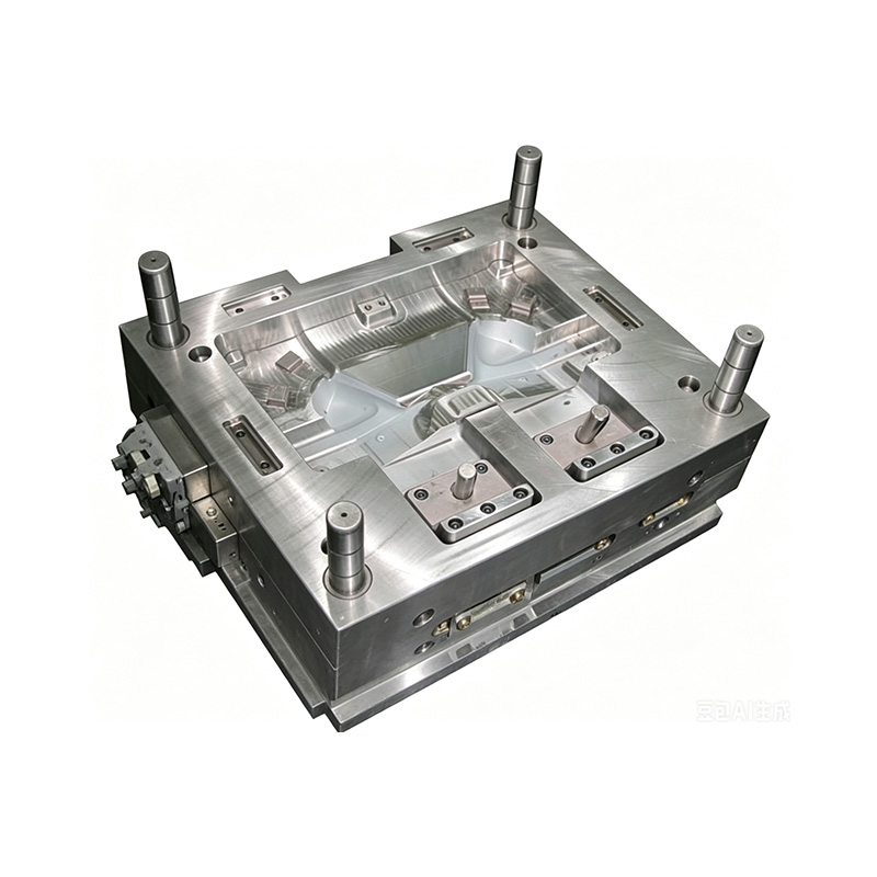
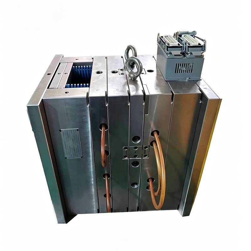
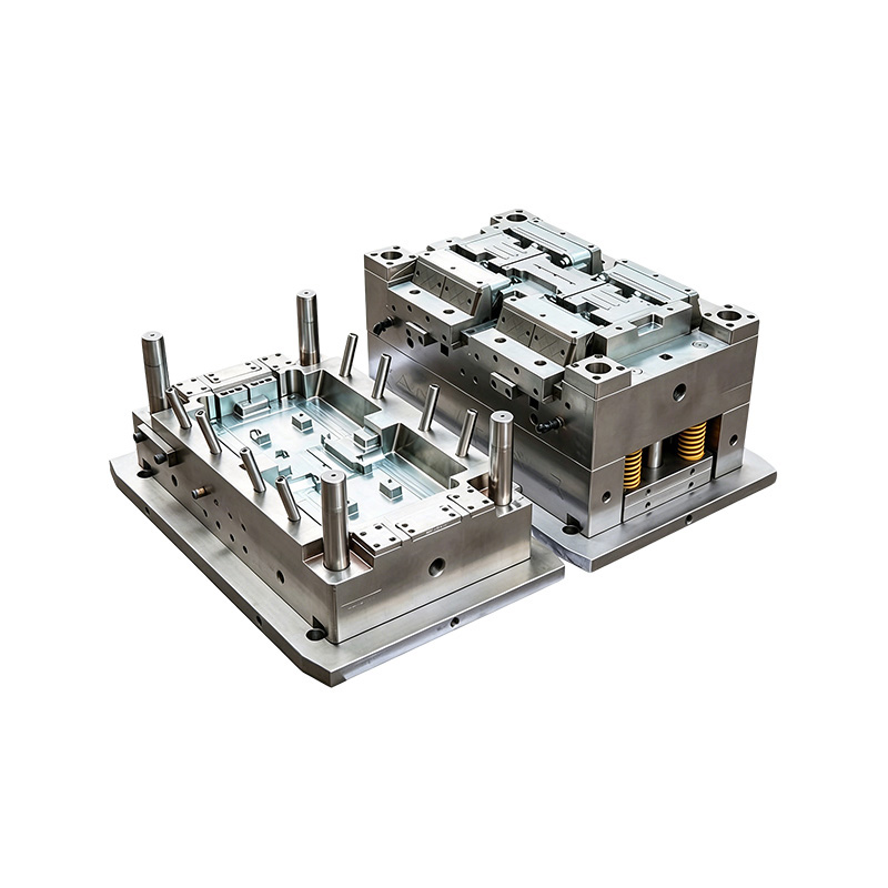
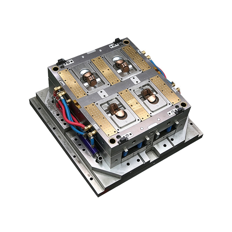
Automotive Part Plastic Injection Molds are the most capital intensive tooling investment in the automotive component supply chain. A single Automotive Part Plastic Injection Mold for a large exterior panel may cost USD 250,000 to USD 800,000 or more, and the mold must deliver consistent part quality across 500,000 to 2,000,000 shot cycles over its production life without requiring dimensional correction or major repair. The design decisions made during the mold engineering phase determine whether the mold achieves this service life at the quality level required, or whether it requires costly modification, refurbishment, or premature replacement.

Mold Steel Selection for Automotive Part Plastic Injection Molds

The steel grade used for the cavity and core blocks of Automotive Part Plastic Injection Molds determines the mold's resistance to wear, corrosion, polishability, and the maximum shot count achievable before dimensional degradation requires rework:

  • P20 (1.2311, 1.2312) pre hardened steel: The most widely used mold steel for medium to long run Automotive Part Plastic Injection Molds producing non abrasive resins (unfilled PP, ABS, PC, TPO). P20 is supplied pre hardened to 28 to 34 HRC and does not require post machining heat treatment, reducing lead time and distortion risk during mold fabrication. P20 Automotive Part Plastic Injection Molds provide acceptable service life of 500,000 to 1,000,000 shots for most unreinforced automotive resins, but wear on gate areas and high velocity flow surfaces becomes apparent above these shot counts for glass fiber filled resins, because the glass fibers in the melt stream are abrasive to the relatively soft P20 steel surface.
  • H13 (1.2344) tool steel hardened to 48 to 52 HRC: The standard steel for high volume Automotive Part Plastic Injection Molds producing glass fiber reinforced resins (PA66 GF30, PP GF20, PBT GF30) where the abrasive fiber content rapidly wears softer mold steels. H13 Automotive Part Plastic Injection Molds for filled engineering resins achieve service lives of 1,000,000 to 3,000,000 shots before gate wear and cavity erosion require repair. H13 requires a careful heat treatment sequence (austenitizing at 1,010 to 1,040 degrees Celsius, triple tempering at 550 to 600 degrees Celsius) and controlled slow cooling to achieve the target hardness uniformly throughout the cavity block cross section without distortion that would compromise the cavity dimensional accuracy.
  • Stainless steel (420 SS, 1.2083) for corrosion resistance: Used for Automotive Part Plastic Injection Molds producing parts from PVC, flame retardant resins containing bromine or chlorine compounds, or resins that off gas corrosive by products at melt temperature. Standard carbon tool steels corrode rapidly in the presence of these resins' processing by products, causing pitting on the cavity surface that reproduces on the molded part surface and requires frequent polishing to maintain part appearance standards. Stainless steel molds for these applications maintain cavity surface quality at significantly lower maintenance frequency than carbon steel alternatives.

Gate Design and Runner Systems in Automotive Part Plastic Injection Molds

The gate (the point where molten plastic enters the mold cavity from the runner system) and the runner system (the channels that distribute melt from the machine nozzle to the gate or gates) are among the most performance critical design elements in Automotive Part Plastic Injection Molds. Gate design errors cause weld lines in structurally critical locations, visible flow marks on cosmetic surfaces, inadequate packing of remote cavity regions, and excessive gate vestige that requires secondary trimming operations.

  • Hot runner systems for automotive injection molding: Hot runner systems maintain the runner channels in the molten state between shots by incorporating electric heaters within the mold runner plate, eliminating the cold runner scrap that cold runner molds produce with each cycle. For automotive injection molding, hot runners are used on virtually all large volume Automotive Part Plastic Injection Molds because they eliminate the material waste of cold runner scrap (which for large automotive parts can represent 5% to 15% of the shot weight) and allow individual gate timing control for multi gate cavities, enabling sequential valve gating that eliminates weld lines from cosmetic surfaces by controlling the flow front meeting point to a non cosmetic location within the cavity.
  • Sequential valve gating for large exterior parts: Large injection molding automotive parts such as bumper fascias and instrument panels require multiple injection gates to fill the full cavity length without excessive fill pressure or flow induced residual stress. Sequential valve gating opens individual gate valves in a timed sequence as the flow front advances through the cavity, ensuring that each gate opens only when the flow front reaches its gate position. This eliminates the weld lines between adjacent gate flow fronts that would otherwise appear as visible lines on the painted exterior surface, which are rejected under automotive Class A surface appearance standards.
  • Edge gate and submarine gate for smaller parts: Smaller interior injection molding automotive parts (clips, connectors, brackets, HVAC louvers) use edge gates or submarine gates where the gate location is hidden on the underside or edge of the part, with the gate vestige trimming during ejection (submarine gate) or in a secondary trim operation. The gate location is specified during part design in collaboration between the mold designer and the part engineer to ensure that the flow pattern from the gate fills all cavity features adequately and that weld lines fall in structurally non critical locations.

Automotive Part Plastic Injection Molds Validation: From T0 to SOP

Every new Automotive Part Plastic Injection Mold goes through a formal validation sequence before it is approved for series production at Start of Production (SOP). This sequence is defined by the automotive industry's PPAP (Production Part Approval Process) standard and involves multiple trial stages each of which produces dimensional and functional data used to progressively confirm that the mold and process will produce conforming parts consistently in series production:

  • T0 (first steel): The first mold trial conducted immediately after the mold is machined and assembled, before any dimensional corrections or surface texturing are applied. T0 establishes the baseline dimensional relationship between the mold cavity and the molded part, identifying any machining errors or shrinkage prediction inaccuracies that require mold rework before the process can be optimized.
  • T1 (after first mold corrections): The second trial conducted after the T0-identified dimensional corrections and any gate or runner modifications have been completed. T1 parts are measured on a coordinate measuring machine (CMM) to verify that the corrections achieved the intended dimensional change and that no secondary dimensional issues were introduced. T1 is typically also when the mold texture (grain) is applied to cosmetic surfaces, as texturing is done at this stage to avoid having to re texture if earlier corrections alter the surface geometry.
  • T2 to Tn (process optimization and PPAP sampling): Subsequent trials optimize the injection molding process parameters (fill speed profile, packing pressure, cooling time, mold temperature) within the Automotive Part Plastic Injection Mold's established capability. The PPAP Level 3 submission requires production of 300 consecutive conforming parts from the production mold on the production machine at the production process setting, with full dimensional measurement (all drawing dimensions) on a minimum of 5 parts from the production run and statistical capability analysis (Cpk above 1.67 for critical dimensions, Cpk above 1.33 for standard dimensions) confirming that the process is capable of consistently producing conforming injection molding automotive parts.

Quality Control in Plastic Injection Molding Automotive Parts Production

Quality control for plastic injection molding automotive parts extends beyond dimensional measurement to include process monitoring, functional testing, appearance inspection, and material verification. The automotive industry's zero defect quality philosophy (reflected in standards such as IATF 16949 and the use of control plans, FMEA, and statistical process control) means that quality escapes — defective injection molding automotive parts reaching the assembly line — are treated as serious supplier performance failures with significant commercial and reputational consequences.

In Process Monitoring for Automotive Injection Molding

  • Cavity pressure monitoring: Pressure sensors embedded in the mold cavity wall measure the melt pressure during the fill and packing stages of each cycle. The cavity pressure curve (pressure versus time) is a sensitive indicator of process consistency: variations in melt viscosity (from resin batch variation or moisture content), clogging of gates or vents, or wear of hot runner valve tips all produce characteristic changes in the cavity pressure curve that can be detected and used to sort or reject suspect parts before they reach the assembly line. Cavity pressure monitoring detects 95% to 99% of process variations that produce dimensional or structural defects in injection molding automotive parts, compared to the 60% to 80% detection rate achievable by end of line dimensional sampling alone at equivalent inspection cost.
  • Vision inspection systems: Machine mounted or end of line vision systems photograph each injection molding automotive part after ejection and compare the image to a reference template, flagging parts with surface defects (sink marks, flash, burn marks, short shots, color variation, or surface contamination) for rejection before they enter the shipping container. Vision inspection at line rate (matching the machine cycle time) allows 100% inspection of cosmetic surfaces on high volume automotive parts, replacing sampling based visual inspection and eliminating the risk of defective appearance parts reaching the customer.
  • Statistical process control (SPC) on critical dimensions: Critical dimensions (those that directly affect vehicle fit, function, or safety) are measured on a statistically defined sampling frequency during production using CMM or dedicated gauge fixtures, and the results are plotted on control charts that display the process mean and variation relative to the dimension's control limits. Control chart rules (Western Electric rules or equivalent) provide early warning when the process is trending toward the specification boundary, allowing process adjustment before defective parts are produced. SPC on critical dimensions is a mandatory requirement of IATF 16949 for all automotive injection molding suppliers.

Functional and Durability Testing for Injection Molding Automotive Parts

  • Thermal cycling tests: Injection molding automotive parts used in temperature cycling environments (all exterior parts, all under hood parts, and interior parts near sunlit surfaces) are subjected to accelerated thermal cycling tests (typically minus 40 degrees Celsius to plus 90 degrees Celsius for interior parts, minus 40 degrees Celsius to plus 120 degrees Celsius for exterior parts, repeated for 1,000 to 5,000 cycles) to verify that differential thermal expansion between joined plastic parts or between plastic and metal inserts does not produce visible distortion, cracking, or separation of bonded surfaces within the test duration equivalent to the vehicle service life.
  • Scratch resistance testing: Interior injection molding automotive parts with Class A cosmetic surfaces (visible to vehicle occupants in normal use) must resist surface marring from contact with fingernails, keys, zippers, and cleaning cloths at the levels specified in OEM scratch resistance test standards (typically a minimum scratch resistance of 2N to 5N on a Erichsen scratch tester without visible whitening or surface damage). PP compounds with scratch resistant modifiers, hard coated ABS, and scratch resistant PC grades are used to meet these requirements in high contact interior locations.
  • VOC (volatile organic compound) and fogging testing: All interior injection molding automotive parts must comply with OEM interior air quality standards that limit the volatile organic compound emissions from plastic materials into the vehicle cabin air. German automobile manufacturers reference standards VDA 270 (odor assessment), VDA 275 (formaldehyde determination), and VDA 278 (organic emissions from vehicle interior components) for interior part VOC qualification. Japanese OEMs reference JAMA guidelines. These tests are conducted on finished injection molding automotive parts in their as molded condition and must be passed before the part is approved for series production use.

Trends Shaping the Future of Automotive Injection Molding

The automotive injection molding sector is being reshaped by three concurrent industry trends that are changing which parts are injection molded, from which materials, and with what process technology. Understanding these trends helps both automotive OEMs and their plastic injection molding automotive parts suppliers anticipate the capability investments required to remain competitive in the next generation of vehicle programs.

Lightweighting: Plastic Replacing Metal in Structural Applications

The drive to reduce vehicle weight for fuel economy improvement and electric vehicle range extension is accelerating the substitution of metal stampings, castings, and extrusions with plastic injection molding automotive parts made from high performance reinforced thermoplastics. Structural injection molding automotive parts applications that were previously considered exclusively metal domains include front end carrier modules (replacing steel stampings with PA6 GF30 structural injection moldings), battery housing and enclosure components (replacing aluminum with PA66 GF50 or continuous fiber reinforced thermoplastic composites), and door inner structures. Each kilogram of vehicle weight reduction from metal to plastic conversion through automotive injection molding produces a fuel economy improvement of approximately 0.5% in a conventional ICE vehicle or a range improvement of approximately 0.3% in a battery electric vehicle, providing the economic and regulatory compliance rationale for the premium material and tooling investment required for structural plastic injection molding automotive parts.

Electric Vehicle (EV) Specific Injection Molding Automotive Parts

Electric vehicles require a different set of injection molding automotive parts than internal combustion engine vehicles, creating new growth opportunities in automotive injection molding for specific part categories:

  • Battery system components: Battery cell holders, module housings, battery management system enclosures, and thermal management channel plates are new automotive injection molding applications with no direct ICE vehicle equivalent. These parts require materials that combine electrical insulation (high dielectric strength), flame retardancy (meeting UL94 V-0 or better), dimensional stability at the battery operating temperature range (up to 60 degrees Celsius continuous), and resistance to electrolyte fluid exposure from cell venting scenarios.
  • Thermal management system parts: EV thermal management systems are more complex than ICE vehicle cooling systems, including active thermal management of the battery pack, power electronics, and cabin, with multiple coolant circuits. The increased number of fluid circuit components (connectors, manifolds, pump housings, valve bodies) creates proportionally higher demand for precision injection molding automotive parts in glass reinforced polyamide and other chemically resistant engineering resins.
  • Charging system components: Charging port housings, DC to DC converter enclosures, onboard charger housings, and cable management components are automotive injection molding applications that are unique to electric and plug in hybrid vehicles and represent a growing category of injection molding automotive parts as the global vehicle fleet transitions toward electrification.

Sustainability Innovations in PP Cosmetic Packaging and Automotive Injection Molding Materials

Automotive OEMs are responding to regulatory pressure and consumer expectations by specifying minimum recycled content in plastic injection molding automotive parts, transitioning to bio based resins where mechanical performance allows, and designing parts for disassembly and material recovery at vehicle end of life. Post consumer recycled (PCR) PP content of 25% to 50% in interior trim components, bio based PA12 from castor oil for fuel system components, and chemically recycled nylon from fishing nets (Econyl) in carpet and textile backed injection molding automotive parts are examples of sustainability material innovations being implemented in production automotive injection molding programs as of 2024 to 2025.

Frequently Asked Questions

1. What is automotive injection molding and how does it differ from general purpose injection molding?

Automotive injection molding is the application of the injection molding process specifically to produce components for passenger vehicles, commercial vehicles, and their subsystems. It differs from general purpose injection molding in five key respects. First, the dimensional tolerances required for automotive injection molding parts are tighter than most consumer product applications, with critical fit dimensions held to plus or minus 0.05 to 0.15 mm to ensure correct panel gap and flush between assembled vehicle body components. Second, the material qualification requirements are more stringent: automotive resins must be approved against OEM specific material specifications that define minimum mechanical, thermal, and chemical resistance properties, and resin changes require formal requalification through the PPAP process. Third, the production volumes are much higher than most general purpose applications, requiring mold designs optimized for multi million shot service lives and process monitoring systems that maintain quality consistency across years of continuous production. Fourth, the part validation process (PPAP) is mandated and documented, with specific submission requirements for dimensional reports, material certifications, and process capability studies. Fifth, the quality system governing automotive injection molding production must be certified to IATF 16949, the automotive specific quality management standard, which has additional requirements beyond ISO 9001 for automotive specific risk management, process control, and customer specific requirements compliance.

2. What are the most commonly used materials for injection molding automotive parts?

The most commonly used materials for injection molding automotive parts are polypropylene (PP) and its reinforced grades, accounting for approximately 32% of total plastic mass in a typical vehicle; ABS and its alloys with polycarbonate (ABS/PC); thermoplastic polyolefin (TPO) for exterior body panels and bumper fascias; glass fiber reinforced polyamide 6 and 66 (PA6 GF30, PA66 GF30, PA66 GF50) for structural and under hood parts; polycarbonate (PC) for optical components including headlamp lenses; thermoplastic elastomers (TPE and TPO) for soft touch surfaces; and specialty engineering resins including PPS, PPA, and PEEK for the most demanding high temperature under hood locations. The selection of the specific material for any injection molding automotive parts application is determined by the thermal, mechanical, chemical, and regulatory requirements of the specific part function and location in the vehicle, using OEM maintained approved resin lists as the baseline specification framework.

3. How are Automotive Part Plastic Injection Molds different from molds for other industries?

Automotive Part Plastic Injection Molds differ from molds for consumer products, packaging, or medical devices in four primary ways. Service life requirements are much higher: automotive molds must deliver 500,000 to 3,000,000 conforming shots depending on the annual volume and vehicle program life, compared to 50,000 to 500,000 shots for typical consumer product molds. Dimensional precision is tighter: automotive exterior panel molds maintain cavity surface accuracy to plus or minus 0.02 to 0.05 mm to achieve the part to vehicle gap and flush specification. Process control integration is more comprehensive: automotive molds routinely include cavity pressure sensors, temperature sensors, and hot runner valve control systems that are monitored and logged for every production shot as quality evidence. Finally, the validation and approval process is more formal: Automotive Part Plastic Injection Molds are subject to a documented trial and approval sequence (T0, T1, PPAP) with customer witnessed trials and documented approval before production release, which is not standard practice in most non automotive molding sectors.

4. What is PPAP and why is it required for plastic injection molding automotive parts?

PPAP (Production Part Approval Process) is the automotive industry's standardized process for confirming that a supplier's manufacturing process is capable of consistently producing a part to the OEM's design specification before series production begins. PPAP is required for plastic injection molding automotive parts because the automotive assembly process cannot tolerate dimensional or functional variation that would cause assembly failures, panel misalignment, or customer visible quality defects at the vehicle level. The PPAP submission for a new injection molding automotive part at Level 3 (the most common requirement) includes: a dimensional report measuring all print dimensions on 5 or more parts from a 300-piece production trial; material certifications confirming the resin meets the OEM specification; a process capability study showing Cpk above 1.67 for critical dimensions; an appearance approval report with OEM confirmation of surface color, gloss, and texture; a control plan documenting how each critical quality characteristic will be monitored in production; and an FMEA (Failure Mode and Effects Analysis) documenting the potential failure modes, their severity, detectability, and the controls in place to prevent or detect each failure mode before it reaches the customer.

5. How long does it take to produce an Automotive Part Plastic Injection Mold?

The lead time to produce an Automotive Part Plastic Injection Mold from mold design approval to T0 trial readiness is typically 8 to 20 weeks depending on the complexity of the part, the size of the mold, the steel grade and heat treatment required, and the workload of the mold making facility. A simple small part mold in P20 steel for a clip or bracket may be produced in 6 to 8 weeks. A complex large part mold in H13 for a door panel or instrument panel with multiple side actions (mold components that move perpendicular to the mold opening direction to form undercut features), integrated hot runner system, and texture ready cavity surfaces requires 16 to 20 weeks. The design phase (mold flow analysis, mold design, customer review and approval) adds 2 to 4 weeks before machining begins, making the total time from part design freeze to T0 trial typically 12 to 24 weeks for automotive program tooling. This lead time is a key constraint in automotive program timing, and delays in part design finalization directly compress the time available for mold validation before the SOP date.

6. What causes weld lines in injection molding automotive parts and how are they eliminated?

Weld lines (also called knit lines) in injection molding automotive parts form where two or more flow fronts of molten plastic meet inside the mold cavity after flowing around a core feature (a hole, a boss, or a through slot in the part) or from multiple gates. At the meeting point, the two flow fronts have lost some of their heat and driving pressure, and the molecular chains at the flow front surfaces are already partially oriented parallel to the flow direction rather than entangled in a random orientation network. This produces a visible line on the part surface at the weld location and a reduction in mechanical strength at the weld (typically 20% to 40% reduction in tensile strength and 30% to 60% reduction in impact strength compared to the unwelded base material for glass fiber filled resins). Weld lines are eliminated or relocated in cosmetic and structural injection molding automotive parts through three design approaches: modifying gate location to direct both flow fronts to meet in a non cosmetic and non structural region of the part; using sequential valve gating to ensure that one flow front catches up with another rather than meeting head on (eliminating the weld line entirely); or redesigning the part geometry to eliminate the core feature that splits the flow front. Mold flow simulation (using software such as Autodesk Moldflow or Moldex3D) predicts weld line location before any steel is cut, allowing gate location and part geometry optimization to be completed in the computer before the mold is manufactured.

7. What is two shot (2K) automotive injection molding and when is it used?

Two shot (2K) automotive injection molding is a process that produces a finished multi material injection molding automotive part in a single integrated production cycle using a single mold, without requiring manual assembly of separately molded components. The process uses a specialized two component injection molding machine with two injection units and a rotating or indexing mold platen: the first shot molds the rigid substrate material in the first mold position, the mold rotates or indexes to the second position, and the second shot overmolds a different material (typically a soft touch elastomer, a different color resin, or a transparent material) directly onto the first shot substrate. The two materials bond at their interface either through chemical affinity (if the substrate and overmold materials are chemically compatible) or through mechanical interlocking (if the substrate has features that the overmold material flows into and solidifies around). Two shot automotive injection molding is used for: soft touch interior trim where a PP substrate is overmolded with TPO or TPE for a premium tactile surface; two color exterior lighting components where the reflector and the light guide are molded in a single cycle; and sealing surfaces where a rigid structural component is overmolded with a flexible seal in a single production step that eliminates the assembly and adhesive processes required for a separately produced seal component.

8. How does mold flow simulation improve Automotive Part Plastic Injection Molds?

Mold flow simulation (computational fluid dynamics analysis of the injection molding process) improves Automotive Part Plastic Injection Molds by predicting the outcome of the injection molding process in software before any mold steel is machined, allowing design changes that would require expensive mold rework if discovered during physical trials to be made at the cost of a software modification and re simulation. Key outcomes predicted by mold flow simulation that guide mold design for automotive injection molding include: fill pattern and time (showing whether the cavity fills completely and uniformly without short shots or race tracking); weld line location (allowing gate locations to be adjusted to move weld lines from cosmetic or structural surfaces); air trap location (identifying regions where trapped air cannot escape through the parting line or vents, which would cause burn marks or incomplete filling); gate and runner pressure drop (confirming that the machine's available injection pressure is sufficient to fill the cavity at the required injection rate); warpage and distortion (predicting the dimensional deviation of the cooled part from the mold geometry due to differential shrinkage, allowing mold compensation to be incorporated into the cavity machining); and cooling efficiency (optimizing the cooling channel layout to minimize cycle time while maintaining uniform mold temperature across the cavity surface). Mold flow simulation reduces the number of physical trial and correction cycles required before achieving a conforming Automotive Part Plastic Injection Mold, with industry data showing an average reduction of 1 to 2 mold trial iterations (saving USD 15,000 to USD 40,000 per avoided trial in machine time, material, and engineering cost) for molds where simulation is used versus molds designed by experience alone.

9. What quality certifications must a plastic injection molding automotive parts supplier hold?

A plastic injection molding automotive parts supplier must hold IATF 16949 certification (the International Automotive Task Force quality management standard for automotive production organizations and relevant service parts organizations) as the minimum quality system certification required by most automotive OEMs and Tier 1 suppliers for production part supply. IATF 16949 is an automotive specific extension of ISO 9001 that adds requirements for automotive specific risk management tools (FMEA, control plans, MSA, SPC), customer specific requirements compliance, production part approval (PPAP), and special characteristic management. In addition to IATF 16949, plastic injection molding automotive parts suppliers may be required to hold: ISO 14001 environmental management certification (required by most European OEMs and many North American OEMs); REACH and RoHS compliance declarations for substance restriction requirements in European markets; and OEM specific supplier quality rating approvals (such as Ford's Q1 status, GM's GP-10 requirement, or Toyota's supplier assessment score) that reflect the OEM's direct evaluation of the supplier's quality performance beyond the base IATF 16949 certification.

10. How is the cost of an Automotive Part Plastic Injection Mold calculated and amortized?

The cost of an Automotive Part Plastic Injection Mold is calculated based on the mold's size, complexity, steel grade, number of cavities, hot runner specification, and side action count, all of which are known from the mold design before fabrication begins. A single cavity mold for a medium complexity interior injection molding automotive parts part in P20 steel with a standard cold runner costs USD 30,000 to USD 80,000. A single cavity mold for a large exterior part with a hot runner and multiple side actions in H13 hardened steel costs USD 150,000 to USD 400,000. A multi cavity family mold producing four small parts in a single shot costs USD 60,000 to USD 150,000 depending on the parts' complexity and the steel grade. Mold cost amortization in automotive injection molding is handled in one of three commercial models: the OEM or Tier 1 customer pays the tooling cost directly and owns the mold (which is then provided to the injection molder as customer supplied tooling); the injection molder funds the mold and amortizes the cost into the piece part price over the contracted annual volume and vehicle program life; or the mold cost is split between customer and supplier on a negotiated basis that reflects each party's volume risk and the strategic value of the supplier relationship. The amortization rate for a USD 200,000 mold over a 5-year program at 100,000 parts per year is USD 0.40 per part in tooling recovery, which combined with the material cost, machine time, overhead, and margin establishes the total piece part price for the injection molding automotive parts production contract.